Return Policy

Due to the low-cost pricing structure of our business, all sales are final, and purchases cannot be canceled once confirmed. We are unable to accept returns or exchanges for any items.
However, we stand behind the quality of our products and offer a one-year warranty on all items. If your product is found to be defective within one year of purchase, we will repair it free of charge. To initiate a warranty repair, please contact our customer service team for further instructions.

Please note that this warranty covers repair of defective items only and does not apply to damages caused by misuse, improper installation, or unauthorized modifications

How To Clean Fiber Connector After Each Use To Prevent Damage

Cleaning optical fiber connectors after each use is crucial to maintaining optimal performance and preventing damage to the fiber system. Here’s a step-by-step instruction for cleaning fiber optic connectors:

Materials Needed:

  • Lint-free wipes or optical-grade cleaning cloth
  • Isopropyl alcohol (99% or higher purity)
  • Dry cleaning tools (e.g., fiber optic cleaning pen or cassette cleaner)
  • Compressed air (optional)

Cleaning Procedure:

  1. Turn off all equipment connected to the optical fiber.
    • Ensure the fiber optic cable is not transmitting any light to avoid potential damage to your eyes or equipment.
  2. Inspect the connector:
    • Visually inspect the connector’s end face under a fiber scope or magnifying lens to check for dirt, dust, or scratches.
  3. Use a dry cleaning method (preferred):
    • Use a fiber optic cleaning pen or a cassette cleaner. Insert the connector into the cleaner and apply gentle pressure while rotating it.
    • For LC, SC, or other connectors, insert the cleaning pen into the adapter and push the tool gently to clean the surface.
  4. Wet cleaning if necessary:
    • If dry cleaning doesn’t remove all contaminants, dampen a lint-free wipe with a small amount of isopropyl alcohol (99%).
    • Gently wipe the connector end face in a straight motion from one side to the other. Avoid circular motions to prevent redepositing contaminants.
    • Follow up with a dry lint-free wipe to remove any residual alcohol or moisture.
  5. Compressed air (optional):
    • If using compressed air, ensure it’s a clean, oil-free source. Hold the connector about 6-12 inches away and blow air across the connector face to remove any loose debris.
  6. Final inspection:
    • Inspect the connector again with a fiber scope to ensure it’s clean and free from any dirt or smudges.
  7. Reconnect the optical fiber:
    • Once cleaned, immediately reconnect the fiber to avoid exposing it to more dust or contaminants.

Tips:

  • Always use clean and fresh wipes or cleaning tools.
  • Never touch the connector end face with your fingers.
  • Store connectors with dust caps when not in use to minimize contamination.
  • Regularly inspect and replace cleaning tools to ensure they remain effective.

By following this routine after each use, you can ensure optimal performance and longevity of your optical fiber connectors.

How To Handle PCB

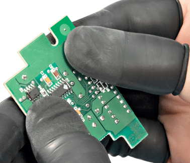
Semiconductors are vulnerable to damage from static electricity generated by the human body. An experimenter has estimated that the human body can have a capacitance of up to 400 picofarads and a charge as high as 50,000 volts. When discharged, such as when touching metal, this can create a spark with an energy of 500 millijoules. Therefore, it is crucial to avoid direct contact with a PCB containing semiconductor devices. Below are some recommendations to prevent static charge damage to these components:


1. Use ESD-rated conductive finger cots when opening and handling the package.
2. Connect the cables to the PCB while wearing the ESD finger cots.
3.Remove the finger cots after the cables are connected.
4. If you need to touch the PCB again, always wear ESD-rated finger cots.


Following these guidelines will help protect semiconductor devices on the PCB from potential static electricity damage.

How To Measure The Return Loss of A Fiber Optical Device

We use the established optical CW reflection (OCWR) method to measure optical return loss.


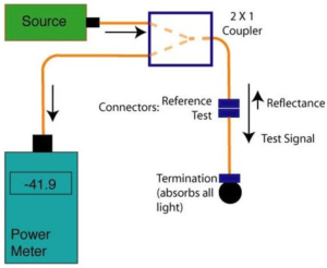
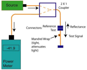
As shown in the figures above, the OCWR Testing setup for reflectance or return loss tests of connectors or passive fiber components per industry standards (TIA FOTP-107 or IEC 61300-3-6) using a light source and power meter. The method sends light from a source through a coupler to the fiber components that are being tested. That connection will typically consist of a reference connector which is used to mate to the connector under test. The light reflected from that connection is split by the coupler, and part is measured by the power meter.
In order to calculate the reflectance or return loss, you need to know the magnitude of the test signal and the split ratio of the coupler, including the excess loss of the coupler. The coupler will reduce the outgoing and reflectance power levels by 3 dB plus some loss due to its inefficiency, typically ~ 3.5 dB.. You must also minimize the reflectance of other components in the cable under test. There are two ways often used to “terminate” or reduce the reflectance from the rest of the cable under test. One method is to use an “optical termination” at the end connector, typically done by inserting the end of the connector ferrule into an index matching gel or liquid. The index matching gel used for mechanical splices works well, but mineral oil or alcohol works fairly well too. The other method is to use a mandrel wrap to reduce the reflectance from other ports. After the test, of course, the connector ferrule needs careful cleaning with pure isopropyl alcohol.

How To Change IP Address of The Euthenist Interface

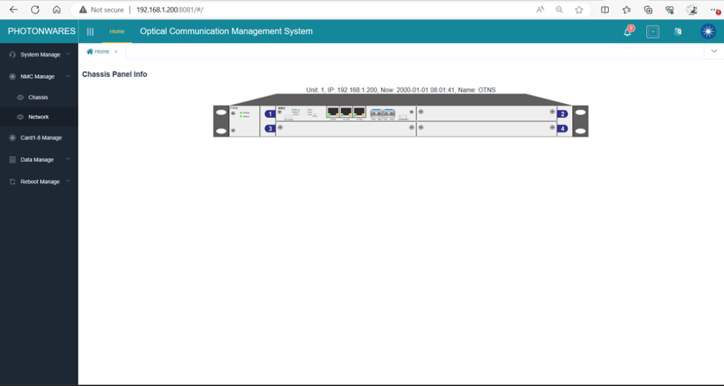
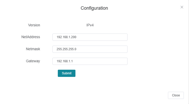
1.  To change the IP address, please login to the web GUI:


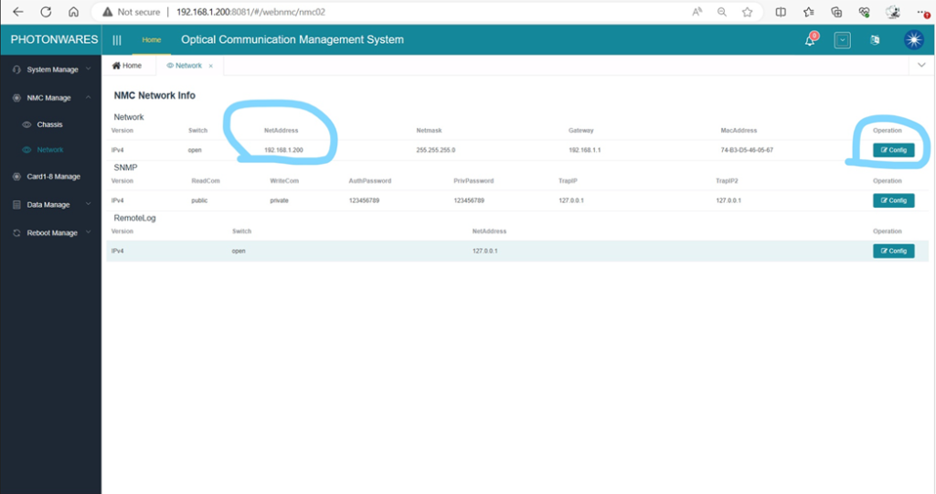
2.   Click ‘NMC Manage’, ‘Network’, on the left side panel you’ll see the Network configuration page:


3.   Click ‘Config’ to change the IP address according to your network settings.

How To Select Variable Optical Attenuator (VOA) Type?

With feedback control, we produce high-precision VOAs that lock the set attenuation value regardless of environmental variations. All types VOAs can be made in this way.
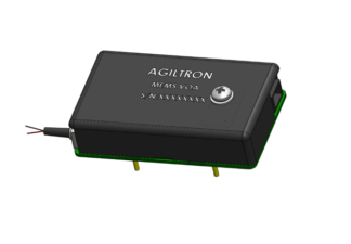
  • High Precision/Repeatability Variable Attenuators (VOAs)

    High Precision/Repeatability Variable Attenuators (VOAs)

    (0.1dB accuracy 1-40dB, 0.6dB accuracy 40-65dB, temperature insensitive)

    $495+
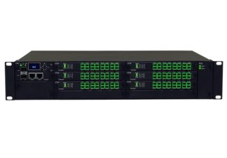
     

  • Programmable VOA Array System

    Programmable VOA Array System

    (Ethernet/SNMP, 350nm to 2600 nm, 0.2dB Loss, 60dB Attenuation, All fiber types, Up to 198 channels)

    $2574+


We uniquely produce MEMS VOA and Fiber-Fiber VOAs that can reach 80dB light blocking level for applications requiring large attenuations.
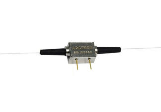

  • MEMS Straight Fiber Optical Variable Attenuator

    (1060 to 2300nm, 0.7dB loss, SM, PM, MM)

    $97$135


If your operation requires VOA with optical loss as small as possible, our Fiber-Fiber VOA is nearly lossless. 0.005 dB insertion loss version is available for purchase.
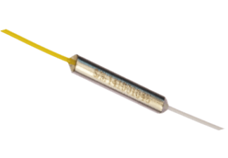
  • Ultra-Broadband Variable Attenuators – Fiber-Fiber™

    Ultra-Broadband Variable Attenuators – Fiber-Fiber™

    (300-2600nm, all fiber types with core 3mm to 1mm, ultra-low loss 0.2dB)

    $123+


We lead the market in high-speed VOAs. Compact integrated modules that take out optical power spikes or regulate the optical power are available.
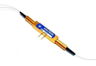
  • High Speed Variable Fiber Optical Attenuators (VOAs) – NanoSpeed™

    High Speed Variable Fiber Optical Attenuators (VOAs) – NanoSpeed™

    (fast: 200ns, 400-2400nm, vibration insensitive, low loss)

    $750+


For high optical power applications, we uniquely produce High Power VOA up to 20 W.
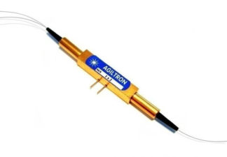
  • High Speed Variable Fiber Optical Attenuator – NanoSpeed™

    (960nm-2200nm, 100kHz, 20db, Bidirectional, SMF, PMF, High Power)

    $750$1,450


For high optical power applications, we uniquely produce High Power VOA up to 20 W.
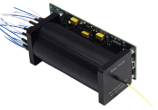
  • Large Core Fiber Variable Optical Attenuator Motor - Fiber-Fiber™

    Large Core Fiber Variable Optical Attenuator Motor – Fiber-Fiber™

    $1120+


We produce the smallest VOA on the market, with a diameter of only 3.2 mm. This family of MEMS VOAs can also operate under a shock/vibration environment.
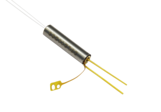
  • MEMS Ultra Mini Variable Optical Attenuator

    (vibration insensitive, fastest/smallest MEMS VOA on the market)


We produce VOA arrays up to 24 channels.

  • Mini MEMS 8 Channel Variable Optical Attenuator Array

    (ultra-compact)


We produce the most comprehensive choice for manual VOAs
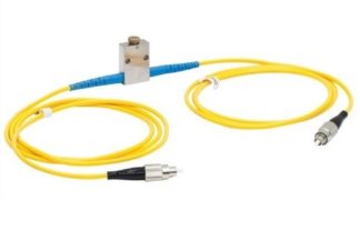
  • Manual Variable Fiber Optical Attenuators

    Manual Variable Fiber Optical Attenuators

    (ultra-broadband 350-2600nm, ultra-low loss 0.3dB, all fiber types: SM, PM, large mode)

    $59+


Perfected over 20 years, we offer the lowest loss, the highest attenuation, the fastest, the smallest, and the most reliable fiber attenuators in the industry. Our thermal actuation MEMS VOAs have the smallest size, the highest attenuation level, and ultra-high reliability. Our Fiber-Fiber™ MEMS series VOAs offer unique performances of near-lossless, ultra-broadband, and all-type fiber compatibility. Our high-precision VOAs have a built-in position sensor achieving high stability/repeatability as well as linearity. For high-speed operation, our solid-state NanoSpeed™ VOAs set an industry-standard in low loss and fast rise/fall, as well as high power handling. The table below guides fiber VOA selection according to your key requirement. All VOAs can be delivered in a turn-key net-ready box. Moreover, we provide custom solutions with in-house micro-assembly and MEMS wafer fabrication.

FC/APC Connector Loss

The coupling loss of a pair of conventional FC/APC connectors is sensitive to its mating conditions. FC/APC connectors made by different vendors have a slightly different angle and end surface shape, thus its insertion loss cannot be assured to meet a specific value unless the customer purchases a pair of specially mated connector from us.

How to Visually Detect Fiber Breakage?

Fiber breakage can be easily detected using a specially-made red laser. This can also be done using a high-power version for fiber cables with heavy jackets. We sell this high-power version Default Locator for $190. Please follow the video below:


Specialized Solutions

In addition to offering premium products that deliver exceptional performance and value, we are committed to providing customized solutions tailored to our customers’ specific needs. If your application requires performance specifications beyond those listed on our website, we invite you to share your detailed requirements. Such requests may involve a one-time Non-Recurring Engineering (NRE) fee to support custom design modifications. Typical lead times are approximately 8 weeks for minor modifications and 12 weeks for complete redesigns. Optowares is supported by an active R&D team — partially funded by the U.S. government — which often substantially reduces the NRE cost. This enables us to deliver advanced, cost-effective solutions that extend beyond current state-of-the-art capabilities.