Ultra-wideband Optical DWDM Digital Transport Network
![]()
- Super T-bit capacity, massive IP service transmission
- Small size, high integration
- Full network intelligent protection, higher reliability
Today’s fiber optic communication networks use dense wavelength division multiplexing (DWDM) to transmit multiple optical signals of different wavelengths over a single fiber, significantly increasing total data throughput beyond the limits of individual transceivers. These wavelengths follow ITU standards for precise channel spacing, enabling interoperability and scalability. In operation, a WDM multiplexer combines multiple laser transmitters into one fiber, while a demultiplexer at the receiving end separates them back into individual channels for detection. Bidirectional transmission is supported, and an optical supervisory channel (OSC), typically operating outside the EDFA band (e.g., 1510 nm or 1620 nm), enables remote monitoring, control, and software upgrades across the network.![]()
Building on this technology, Agiltron’s Ultra-wideband Optical DWDM Digital Transport Network is a highly integrated, carrier-grade platform designed for high-capacity, long-haul applications. It supports single-channel data rates from 100 Mbps up to 400 Gbps, scalable to 800 Gbps, and delivers ultra-terabit capacity across up to 96 DWDM channels in unidirectional or bidirectional configurations. The system enables efficient large-granularity transport with support for 10G, 100G, 200G, and 400G hybrid services, while achieving transmission distances of up to 2,000 km without electrical regeneration. Its modular chassis, available in 1U, 2U, 3U, and 5U formats with up to 20 service slots, provides flexible deployment and high-density integration, including advanced MUX and ODUK processing. Designed for maximum reliability, it features full 1+1 redundancy across client, wavelength, and line interfaces as well as power supplies. Managed by the AG600 network management system, it offers unified, end-to-end control with comprehensive fault, performance, configuration, and security management, delivering a scalable, transparent, and robust solution for modern optical transport networks.
-
 This product has multiple variants. The options may be chosen on the product page
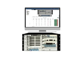
Network Management System Software
Visual Monitoring, Centralized Management and Intelligent Analysis
$980+
SKU: NMS
$980 -
 This product has multiple variants. The options may be chosen on the product page
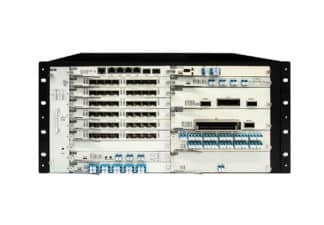
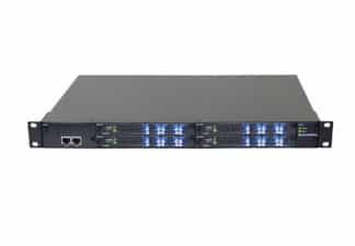
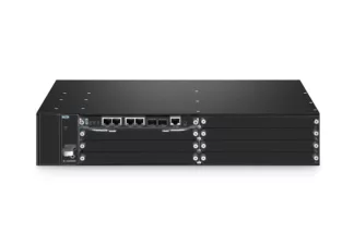
Network Management System Chassis
Support DWDM with each channel 200G/400G, Up to 3.2Tbps Capacity, Redundant AC PSUs
$420+
SKU: RMTP
$420 -
 This product has multiple variants. The options may be chosen on the product page
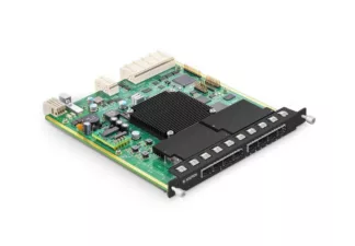
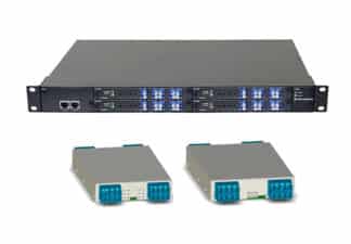
100G Transmultiplexer Unit TMUX OTU
$895+
SKU: TMUX
$895 -
 This product has multiple variants. The options may be chosen on the product page
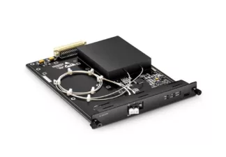
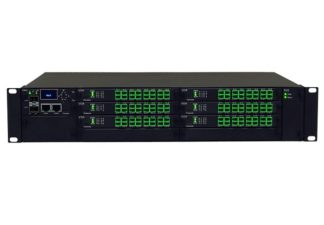
EDFA Amplifiers (OPA, OBA) 1528-1565nm
up to 96 channels c-band, preamplifier, boost amplifier, flat gain
$1402+
SKU: RMEA
Price range: $1,402 through $1,511 -
 This product has multiple variants. The options may be chosen on the product page
Bidirectional EDFA Amplifier (OPA, OBA) 1528-1568nm
22-32dB gain, DWDM, data-rate: 200Gb
$5950+
SKU: BEDF
$5,950 -
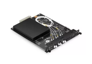
Optical Transport Unit (OUT)
8x10G SFP, 8x25G SFP, 18CWDM, 96DWDM
SKU: ROTU
-
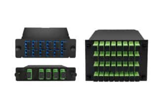
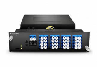
LGX DWDM Mux/Demux Module
100 GHz up to 48 Channels
SKU: LGXW
-
 This product has multiple variants. The options may be chosen on the product page
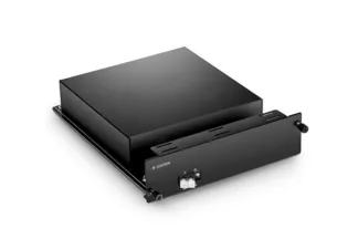
Fiber Dispersion Compensation Module (DCM)
Matches Fiber Length
$704+
SKU: RDCM
Price range: $704 through $987 -
Network Protection Switches -ns Ultrafast Restoration
SKU:
-
 This product has multiple variants. The options may be chosen on the product page
Optical Line Protection (OLP) Module
Automatically Switch To A Spare Fiber, If Signal Reduced
$538+
SKU: OLP
$538 -
 This product has multiple variants. The options may be chosen on the product page
Fiber Optical Switch
Bidirectional, Passive, up to 1x168, 70dB on/off
$1280+
SKU: MEMS
Price range: $1,280 through $1,860 -
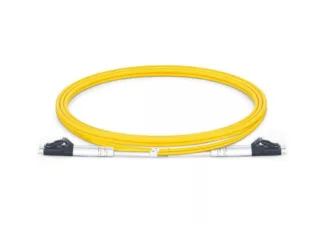
Optical Patch Cord
LC, SC, FC, MTRJ
SKU:
-
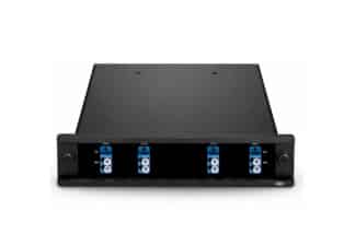
Optical Add/Drop Multiplexer (OADM)
10G/100G/200G/400G, Up to 16 DWDM Channels, Bidirectional
SKU: OADM
-
Cascaded Optical Add/Drop Multiplexers OADM
Single Fiber Bidirectional, 100GHz, Up to 16 DWDM Channels
SKU: COADM
-
Bidirectional Optical Add/Drop Multiplexers OADM
100GHz, Up to 16 DWDM Channels, Single Fiber Bidirectional
SKU: BOADM
-
Hub and Spoke Optical Add/Drop Multiplexers OADM
Single Fiber Bidirectional, 100GHz, Up to 16 DWDM Channels
SKU: HOADM
-
Customized Managed Chassis
4 Slots/1U, 7 Slots/2U, 15 Slots/5U, Dual Power Supplier, Ethernet/SNMP
SKU: RNMC
-
Network Modules/Instruments
SKU: