Compact Low Voltage Free Space Electro-Optical Pockels Cell Modulators: Phase or Intensity
 Our Electro-optic modulators are based on a special crystal that has less piezo-effect and low charge migration than the traditional Mg doped Lithium Niobate crystals, resulting in clean response with less ringing, more efficient with less power consumption, the ability to work at shorter wavelength and higher optical power. We produce two versions: resonant and direct driving. Both modify the phase, polarization or amplitude of a free-space laser: The resonant modulator drastically reduces driving voltage so that it can be driven by a laboratory function generator. Each device uniquely has three fixed resonance frequencies of 1MHz, 15MHz, and 30MHz that can be manually select via a toggle switch. Our resonance electro-optic modulator is a cost effective and convenient device for testing applications. Custom frequencies up to 100MHz are also available. Another version is direct driving modulator that can be operated from DC to high frequencies. However, it needs a high voltage driver which determines its performance. We produce a high-voltage driver. Customer can use drivers from other manufacturers.
- 3 mm Aperture
- Wide Operation Wavelength 450 to 1550 nm
- High Optical Power Handling
- Low Driving Voltage ~12V (resonance)
- One Device with Three Frequencies To Select (1, 15, 30MHz)
- High Repetition Rate Up to 100MHz (Resonance)
- Broadband DC to 1MHz (non-Resonance)
- Fiber Coupled Available
- Customization Available
-
 This product has multiple variants. The options may be chosen on the product page
Amplitude/Phaser Electro-Optical Pockels Cell Modulator – No Resonance
3mm aperture, 450~1550nm, DC to 1MHz, need high voltage driver
$1801+
SKU: EOMN
Price range: $1,801 through $13,617 -
This product has multiple variants. The options may be chosen on the product page
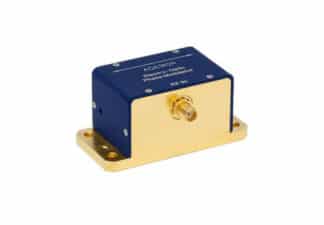
Amplitude/Phaser Electro-Optical Pockels Cell Modulator – Resonance
3mm aperture, 450~1550nm, fixed frequency at 1-20 MHz
$1956+
SKU: FEOM
Price range: $1,956 through $6,970 -
This product has multiple variants. The options may be chosen on the product page
GHz Phase Modulators – Resonance
1-3.05 GHz, temperature control option
$5053+
SKU: GHZM
$5,053 -
 This product has multiple variants. The options may be chosen on the product page
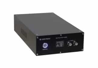
High Voltage Electro-Optical Pockels Cell Modulator Driver
up to 400V
$2548+
SKU: HVED
Price range: $2,548 through $3,588
Electro-Optic Modulators Application Note
Overview
Electro-optic modulators allow one to control the amplitude, phase, and polarization state of an optical beam electrically. Unlike direct modulation of the laser itself, external modulators do not cause any degrading effects on laser linewidth and stability. In measurement or sensor systems, amplitude modulators can be used to maintain the intensity in a laser beam constant, or as optical choppers to produce a pulse stream from a CW laser beam. Phase modulators are used to stabilize the frequency of a laser beam, or to mode-lock a laser. Agiltron electro-optic modulators using, LiNaO3, LiTaO3 and RTP— crystals with high electro-optic coefficients. These crystals have a wide transparency window and non-hygroscopic so they can be left in ambient for indefinite periods. The Agiltron electro-optic Modulators combine high performance at modulation frequencies up to 250 MHz with simplicity in operation that are well-suited for applications with high optical powers or broad spectral bandwidth requirements. Understanding how these modulators work and how to work with them will allow one to make measurements and develop systems in the most efficient and accurate way.
Limitations
There are limits on the performance of these devices. At high optical power or short wavelength, electro-optical crystals are limited by an effect known as photorefractive damage, which degrade the performance of a modulator, especial at high optical power level or shorter wavelengths. The photorefractive effect is most severe with LiNbO3 even with magnesium-oxide (MgO) doping, LiTaO3 has reduced effect, RTP has little. However, RTP is expensive. This new RTP material exhibits far superior power-handling capability and shortwave operation compatibility. Another limitation results from the fact that all materials with nonzero electro-optic coefficients are also piezoelectric. This means that the same electrical signal that produces phase modulation also generates vibrations. Strains induced by these vibrations alter the indices of refraction via the elasto-optic effect. These vibrations can cause unwanted amplitude modulation or beam displacements at the modulation frequency. In comparison, LiNbO3 has the highest piezoelectric constants, LiTaO3 is fairly weak, while RTP has little. The piezo effect affect the performance of the crystals due to the mechanical resonance frequencies (typically between 1 and 10 MHz). Agiltron use LiTaO3 as a general material that has much less adversary effect that the conventional bulk modulator made of LiNbO3 . For high power or short wavelength, we use RTP.
The Electro-Optic Effect
Agiltron uses crystals with linear electro-optic effect that is the change in the index of refraction proportional to the magnitude of an externally applied electric field. This effect is small. For example, an electric field of 106 V/m applied to a crystal of lithium niobate will produce a fractional index change of roughly 0.01%.
Phase Modulation
The phase modulator is the simplest electro-optic modulator. Here, an electric field is applied along one of the crystal’s principal axes.3 Light polarized along any other principal axis experiences an index of refraction change, hence an optical path length change, that is proportional to the applied electric field. The phase of the optical field exiting from the crystal therefore depends on the applied electric field. The most common bulk phase modulator is the transverse modulator, as shown in Figure 1, which consists of an electro-optic crystal between parallel electrodes. These modulators develop large electric fields between the electrodes while simultaneously providing a long interaction length, l, in which to accumulate phase shift.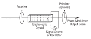
Figure 1: A transverse electro-optic phase modulator. In the case shown, the input beam is polarized in the direction of the electric field within the crystal. The signal is applied as a voltage across electrodes on the top and bottom of the electro-optic crystal.
A commonly used figure of merit for electro-optic modulators is the half-wave voltage, Vπ. It is defined as the voltage required to produce an electro-optic phase shift of 180°. Substituting into the preceding equation yields for a transverse phase modulator.
It is important to note that the properties of a phase-modulated optical beam do not differ in any way from those of any other phase-modulated carrier wave.4 Most importantly, phase modulation cannot be separated from frequency modulation. The instantaneous frequency of a periodic signal is defined as the time derivative of the overall phase of the signal.
Here, most of the optical power resides in the Fourier component, called the “carrier,” at frequency ω, with a small amount of optical power residing in the two first-order sidebands at frequencies ω±Ω. This frequency-modulating property makes phase modulators useful in laser mode-locking.5
Amplitude Modulation
To understand the operation of an electro-optic amplitude modulator, let’s first consider an electro-optic waveplate. Suppose an optical beam, polarized at 45° to the crystal’s principal axes, travels parallel to the third axis of an electro-optic crystal. With no applied field, the crystal is generally an arbitrarily retarding, multiple-order waveplate.6 When an external electric field is applied, the electro-optic effect changes the indices of refraction 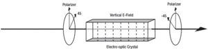 along the two crystal directions to a different degree, thereby changing the retardation of the effective waveplate.
Figure 2: An amplitude modulator in its simplest form consists of an electro-optic crystal between two crossed polarizers. The signal is applied as a voltage across electrodes on the top and bottom of the electro-optic crystal.
The geometry of a simple amplitude modulator, as shown in Figure 2, consists of a polarizer, an electro-optic crystal cut for zero retardation, and an analyzer. The input polarizer guarantees that the optical beam is polarized at 45° to the crystal’s principal axes. The crystal acts as a variable waveplate, changing the exit polarization from linearly polarized (0° rotated from the input) to circularly polarized, to linearly polarized (90° rotated), to circular, etc., as the applied voltage is increased. The analyzer transmits only the component of the exit polarization that has been rotated, thereby producing a total transmission of 0, 0.5, 1, and 0.5 respectively. The relationship between the transmission and applied field is not linear but rather has a sin2 dependence. To obtain linear amplitude modulation, these modulators are often biased at 50% transmission and only operated with small applied voltages. Two ways to bias the modulators are by one, adding a DC voltage through a bias tee, or two, adding a quarter-wave plate before the analyzer. The voltage required to bias the modulator at 50% transmission without a quarter-wave plate is the quarter-wave voltage of the modulator. It has a similar form to the quarter-wave voltage of the transverse phase modulator.
This simple geometry is not practical with most electro-optic crystals, due to the temperature dependence of these crystals’ birefringence. This dependence introduces a temperature-dependent waveplate into the modulator. Consequently, the transmission of an uncompensated modulator using birefringent nonlinear media (such as LiNbO3) will exhibit substantial thermal drift. This temperature sensitivity can be overcome by either stabilizing the temperature of a single-crystal modulator, or by using two identical crystals. The second scheme employs two equal-length crystals placed optically in series with their principal axes rotated 90° with respect to each other, as seen in Figure 3. The optical beam’s polarization components therefore travel equal path lengths in each of the two index regions, which leads to a structure with zero birefringence, independent of 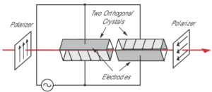 temperature. Thermal drift limits the usefulness of a phase modulator, which is typically made out of a single crystal.
Figure 3: Thermal bias drift can be passively compensated using two crystals oriented orthogonally with respect to each other. In the case shown above, the crystals are mounted at 45°. Thus, the input polarization is vertical. The applied field is reversed in the second crystal. In this manner, the thermal birefringence is compensated but the desired birefringence is doubled.
Amplitude Modulator Transfer Function
The transfer function of an amplitude modulator between crossed polarizers is a sin2 function. You can achieve linear amplitude modulation with small 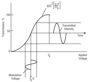 modulation voltages by biasing the modulator at the 50% transmission point, either with a quarter-wave plate or by applying a DC voltage to the modulator.
Resonant Modulators
Many applications require modulation at a single, fixed frequency. The frequency required in the specific application can vary from a few kilohertz to many gigahertz. In these cases, true impedance matching can be achieved, and the required drive voltage can be reduced, by using a resonant circuit. The simplest type of resonator is the LC tank, shown in Figure 6. In this circuit, a modulator crystal and a low-loss inductor are used to form a series resonant circuit. On resonance, the resonant circuit looks like a small resistor whose value depends on the inductor’s losses. The transformer is used to match this resistance to the 50-Ω driving impedance. By impedance matching to the source, and using low-loss components, the voltage across the capacitor can be more than ten times greater than the input voltage, leading to reduced half-wave voltages when compared to a broadband modulator. This reduced voltage requirement is made possible by the energy storage properties of the resonant circuit.
Two factors limit the performance of the lumped-element resonator. The first is the power-handling capabilities of the inductor. Saturation of the inductor core places a limit on the RF-input power that can be used to modulate the optical beam. Also, most of the power dissipation occurs in the inductor and excessive input power will burn it out. Secondly, at frequencies greater than 50 MHz, ordinary lumped circuit elements are difficult to make. Circuits with dimensions comparable to the operating (RF) wavelength are efficient radiators, and therefore very difficult to analyze. Furthermore, conventional wire circuits tend to have a high effective resistance due to radiative energy loss as a result of the skin effect. Enclosures completely surrounded by conducting metal confine electromagnetic fields and furnish large areas for current flow, simultaneously eliminating radiation and high-resistance effects. Such cavities have natural resonant frequencies, and can be used to replace resonant circuits at high frequencies.9 Agiltron offers cavity-resonant, single-frequency modulators out to 10 GHz, a frequency limited by the increasing RF losses in the electro-optic material itself.10
Applications for single-frequency modulators are quite varied. In the audio regime, these modulators are used in fiberoptic sensor and interferometric applications as well as in low-frequency lock-in detection schemes. Medium- to 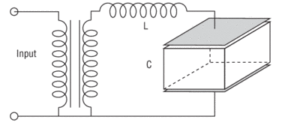 high-frequency modulators (to 250 MHz) find applications in mode-locking (AM and FM), laser stabilization, phase-sensitive detection, and pump-probe detection schemes. Modulators with frequencies to 10 GHz find applications in FM spectroscopy, laser stabilization, and laser linewidth-broadening experiments.
Figure 6: A simplified impedance-matching circuit for the resonant modulators.
Optical Chopping With Amplitude Modulators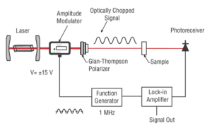
One application of these modulators is high-frequency optical chopping. Although mechanical choppers are frequently used, they modulate the optical intensity at rates of only a few kilohertz. This frequency is often not high enough to get away from the 1/f noise of the detection system. An optical amplitude modulator, such as the Model 410X can be used to chop the beam at 1 MHz, thus giving you shot-noise-limited detection.
Amplitude Stabilizer Application
Another common use for an amplitude modulator is as the actuator in an amplitude stabilizer as shown. Here, a photodetector measures a portion of 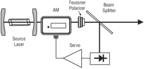 the laser intensity which the servo uses to adjust the transmission of the amplitude modulator. An important consideration in this application is the nonlinear response of the modulator. The changing slope of the modulator’s response to input voltage leads to a change in the closed-loop transfer function which could destabilize the feedback loop. An amplitude modulator can be used to reduce the amplitude fluctuations.