Unlike single-mode laser, multimode light tends to spatially spread out in which each mode has its own distribution pattern and propagates light path. Therefore, without knowing the modal distribution, the measurement results can be drastically different using a different light source. For example, a collimator that focuses a single-mode laser to a small spot of 0.1 mm may only achieve a spot size of 8 mm for a LED source. Another common example is a multimode fiber optical device measured with 1 dB loss by the manufacturer can have 5 dB loss using a different laser at the customer site.
The solution is to use the same light source to design, fabricate, and test the device. This will result in accurate and reproducing performance. A more convenient way is to use light sources with the same quantitively measured modal field number. There is a simple way to characterize the light source that everyone can perform using regular tools. Coupled Power Ratio (CPR) power ratio is an easier metric to understand and to do the test, although it has many deficits (a better way is available but more complex to do). It simply measures the propagating loss difference between a multimode fiber and a single-mode fiber. The following lists the measurement steps.
1. Preparation
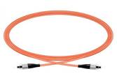
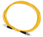
Make two patch cords (jumper cables). One patch cord uses the same MM fiber as in your applications. Another patch cord uses SM28 single mode (SM) fiber.


2. First measurement (MM)
Connect the MM cable to a power meter as in Figure 1, and zero the meter.
(Note: Keep the patch-lead as straight as possible, as could affect the modal power distribution and hence the measurement accuracy).

3. Second measurement (SM)
Leave the MM lead connected to the light source, connect the MM cable to the SM cable on one end and connect the other end of the SM to a power meter, as in Figure 2. Make a 30 mm diameter loop, which acts as a mode filter. Measure & record the power output (L2) of the MM to SM pigtail combination.

1. CPR coefficient calculation
As meter was zeroed the CPR = – L2 (dB)
(Note: Otherwise, the CPR coefficient is calculated as CPR = L1 – L2)
For reference, an FP laser with 50/125 fiber has a CPR of about 10-14; and a LED with 50/125 fiber has a CPR of about 20-26
