, 5ns Fast Recovery 1")
SKU: OLP
The optical Line Protection Switching System (OLP) uses a redundant optical fiber route as a backup path. We uniquely offer a high data rate of up to 200 gigabit and fast optical switching to reduce data loss with three choices of optical switching speed: ms to a few ns. By real-time monitoring the power status of both transmission and receiving in the working fiber, it can automatically switch to the backup fiber when the power value is lower than a user-defined threshold. This design allows the switch to operate independently without communicating, reducing reaction time. Moreover, our system has a built-in laser and detector to monitor the spare fiber line, ensuring its integrity at all times and sensing an alarm when a problem occurs. Our net-ready OLPs offer various reliable protection schemes against fiber cuts and network failures. Our OLP is also compatible with 1310/1550 transmission in the opposite direction in the same fiber. They are used to protect the backbone and important business lines. Management of the OPS is performed using a Web GUI, reachable through the local Ethernet ports on the OPS system control card.
OLP 1:1 Configuration
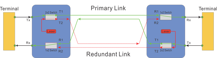
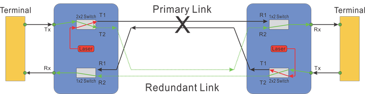
OLP configuration 1:1, as shown in the diagram below, consists of the main fiber route and a standby fiber route between the two sites and associated fiber optical switches. In normal operation, the data are transmitted and received through the main route. Inside the OLP pair, detectors are incorporated at Rx ports to detect the decreasing of the optical power. When a fault is detected on the main route, the system will switch both the transmitting and receiving from the main route to the standby route. This is accomplished by first turning off the built-in test laser so that both ends detect fault. The advantages of a 1:1 OLP system are low optical insertion loss with direct signal passthrough, and the optical fiber for the backup path can also be used for other businesses. The disadvantage is conventional systems require CPU processing the information at both ends, resulting in typically delays of about 80ms in response.
OLP 1+1 Configuration
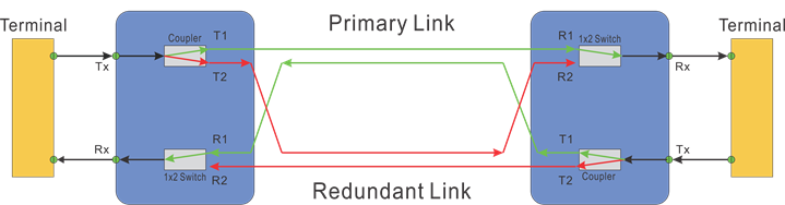
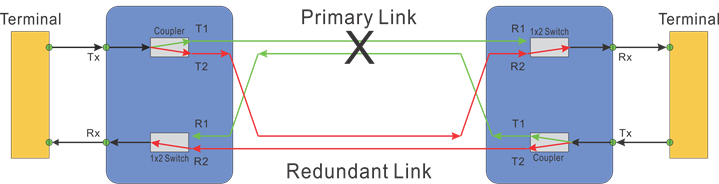
OLP 1+1 configuration is shown in the following diagram, in which the optical signals are split into two with a ratio of 50:50 and transmitted through both main and standby routes at the same time. While for Rx, the optical signal with better quality will be selected when a fault is detected. The advantage of the OLP 1+1 system is faster recovering optical switching. We offer a 100ns recovery option in this configuration. However, there will be a larger insertion loss compared with the OLP 1:1 system.

Reviews
There are no reviews yet.